Contactless water level sensor

This experiment shows that it is possible to detect water level without any electrical contact using ESP32 module, OLED and two aluminium foils.

In this sketch, the ESP32 module generates a sine wave that is transferred by a capacitor to an analog input of the ESP32 connected to a voltage divider. The capacitor is built using two aluminium foils and a glass filled with water. The glass is useful for the experiment, while in the real life there will be a plastic pipe. Make sure that there is no electrical contact between the two aluminium foils.

The peak-to-peak voltage value measured during each sampling window provides an indication of the presence of the water in the glass (or in the plastic pipe). At the end of each sampling window, the peak-to-peak value is smoothed by a Moving Average filter before being displayed as progress bar on OLED display:


This project is available also in Fritzing web site.

Hardware set-up

Following hardware is required to build the experiment:
  • ESP32 module, e.g. LOLIN32
  • OLED display with SSD1306
  • Two aluminium foils and a glass (or a plastic pipe)
  • 2 resistors 100Kohms
Implement following connections:
  • Connect GND(ESP32) together GND(OLED) and R1 (100Kohm resistor)
  • Connect 3V3(ESP32) together with Vcc(OLED) and R2 (100Kohm resistor)
  • Connect R1 and R2 to get a voltage divider
  • Connect an aluminium foil to the voltage divider and to GPIO34(ESP32)
  • Connect another aluminium foil to GPIO25(ESP32)

Confused about all acronyms? Here is a brief explanation: GND is the ground line, 3V3 and Vcc are the positive supply line, GPIO34 is the ADC1 channel 6 input (GPIO is generic purpose Input/Output).

The following picture shows the breadboard for the contactless water level sensor:
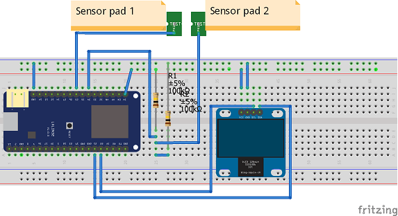
Water sensor breadboard

ESP32 software

Before writing software make sure to have installed the software development environment, downloadable from Arduino Software web site. It may be needed to download some library if not already present. Libraries are required also to manage the external devices.

The sketch is based on sine generator created by Krzysztof.

The loop() function implements the water sensor functionality.

void loop() { unsigned long nextWindow = millis() + sampleWindow; // start of next sample window unsigned int peakToPeak = 0; // peak-to-peak value unsigned int signalMax = 0; unsigned int signalMin = 4095; unsigned int n_samples = 0; unsigned long accvalue = 0; // get peak to peak value during sampleWindow while (millis() < nextWindow) { unsigned int sample = analogRead(analogInputPin); n_samples++; accvalue += sample; if (sample > signalMax) signalMax = sample; else if (sample < signalMin) signalMin = sample; delayMicroseconds(100); // pauses for 100 microseconds before next sample } peakToPeak = signalMax - signalMin; // double volts = (peakToPeak * 3.3) / 4096; // convert to volts //implement Moving Average filter MAF_acc += peakToPeak - MAF[MAF_idx]; MAF[MAF_idx] = peakToPeak; MAF_idx++; if (MAF_idx == MA_size) MAF_idx = 0; int MAF_output = MAF_acc / MA_size; int progress = MAF_output / attenuation; if (progress > 100) progress = 100; display.clear(); // draw the progress bar display.drawProgressBar(0, 32, 120, 10, progress); // write the buffer to the display display.display(); }


Download the complete sketch here and enjoy it.

Share Share on Facebook Share on Twitter Bookmark on Reddit Share via mail
Creative Commons Attribution-Share Alike | Terms and conditions | Privacy policy